
- Home
- Selective Laser Sintering
- SLS 3D printing for jigs, fixtures and robotic grippers
SLS 3D printing for jigs, fixtures and robotic grippers
Jigs, fixtures, and robotic tooling don’t always need to be made from metal.
For many automation and industrial applications, SLS 3D printing provides a practical way to manufacture lightweight, durable tooling without machining it from billet or investing in dedicated tooling.
The process is particularly useful for jigs, fixtures, positioning nests, robotic grippers and end-of-arm tooling because components can be designed around the application, produced directly from CAD and changed quickly when the production process changes.
But SLS isn’t right for every piece of tooling.
The key is understanding where its combination of geometry, material performance and low-volume economics provides an advantage, and where a machined component remains the better choice.
Is SLS suitable for jigs and fixtures?
Yes. SLS is widely used for jigs, fixtures and manufacturing aids where the loads, temperatures and operating environment are suitable for the material.
Unlike some 3D printing processes, SLS doesn’t require separate support structures. The surrounding powder supports each layer during the build.
This gives designers considerable freedom to create complex tooling geometry.
A jig can include locating features, cable routes, handles, labels, mounting points and other functionality in one printed component instead of being assembled from numerous conventional parts.
For frequently changing production environments, that flexibility can be extremely useful.
Why use 3D printing for production tooling?
Traditional tooling often starts with the manufacturing method.
A component is designed so it can be milled, turned, fabricated or assembled economically.
3D printing changes that conversation.
Instead of asking “How can we manufacture this shape?”, the designer can start with “What shape would make this tool work best?”
For jigs, fixtures and robotic tooling, that can lead to some useful improvements.
More freedom to design around the component
A fixture can follow the shape of the part it needs to locate.
A gripper finger can incorporate a contact surface specifically designed for the component it handles.
A sensor bracket can follow the available space around neighbouring machine elements rather than requiring a simple rectangular form.
This can be particularly helpful in crowded automation cells where there’s little spare space.
Lower weight
Metal tooling can add significant weight to the end of a robotic arm.
Replacing suitable metal components with polymer SLS parts may reduce that mass.
Lower weight can be useful when trying to reduce the load on the robot or when the end-of-arm assembly contains several tools, sensors and actuators.
Weight should never be considered independently of strength and safety, however. The complete load case still needs to be assessed.
Combining several parts into one
SLS can often consolidate features that would otherwise require several machined or fabricated components.
Mounting features, cable clips, locating surfaces and internal passages may be incorporated into the same design.
Reducing the number of individual components can simplify an assembly and reduce the number of joints, fixings and interfaces that need to be managed.
Faster design changes
Automation projects have a habit of changing.
A customer’s component is revised. A sensor moves. A pneumatic fitting changes. A conveyor layout is adjusted. A pick-and-place routine exposes a small interference that did not appear in CAD.
With a 3D printed tool, the digital model can be modified and a revised version manufactured without remaking conventional tooling.
That makes SLS well suited to development environments where iteration is expected.
What automation parts can be made using SLS?
Typical applications include:
Robotic gripper fingers
Custom gripper fingers can be shaped around the component being picked up.
This can increase the contact area and allow features to be added that help locate or protect the workpiece.
Polymer contact surfaces can also be useful when handling components where a metal gripper might mark the surface, although suitability will depend on the workpiece and operating conditions.
End-of-arm tooling components
End-of-arm tooling often contains considerably more than the gripper itself.
Brackets, covers, sensor mounts, manifolds, cable guides and lightweight structural elements may all be candidates for SLS.
Complex routing features and mounting geometry can be built directly into the component.
Assembly jigs
A jig used during manual assembly may only need to locate several components in the correct position while an operator carries out another task.
Producing it using SLS can be faster and simpler than machining a complex nest from a block of plastic or metal.
Inspection fixtures
SLS can also be useful for fixtures used to hold a component consistently during visual or dimensional checks.
Critical locating features should be designed and validated carefully, particularly where inspection results depend on the fixture itself.
Positioning nests
A nest can be created to closely follow the shape of an irregular workpiece.
This is useful in assembly, handling and automated loading applications where repeatable positioning is important.
Sensor and camera brackets
Automation systems frequently acquire additional sensors, cameras or inspection equipment during development.
Small SLS brackets can provide a quick way of testing positions and angles before a final configuration is established.
Cable and hose management
Cable guides, clips, protective covers and hose-routing components are another useful application, particularly where standard catalogue parts don’t fit the available space.
What material does Prototype Projects use for SLS?
We use PA 2200 CarbonReduced, a sustainable PA12 material.
It combines high strength and stiffness with abrasion resistance and long-term dimensional stability, making it suitable for a range of functional components as well as prototypes.
Parts are produced in white as standard and can also be finished where required.
For automation applications, the relevant question is not simply whether PA12 is “strong”.
The part should be assessed against the conditions it will actually experience, including:
- Static and dynamic loads
- Repeated cycles
- Temperature
- Impact
- Wear
- Chemical exposure
- Required stiffness
- Safety implications if the component fails
Where those requirements exceed what a polymer SLS component can reasonably provide, CNC machining may be the better choice.
Can SLS produce internal air or vacuum passages?
One of the useful features of SLS is its ability to produce complex internal geometry that would be difficult to machine conventionally.
That can include channels and manifolds for vacuum or compressed air.
For robotic tooling, this creates opportunities to integrate air routing into a component instead of assembling it from separate drilled blocks, fittings and tubes.
There are still practical limitations.
Channels need to be designed so that unfused powder can be removed after manufacture, and the required pressure, sealing performance and wall thickness need to be considered.
If an internal passage is critical to the operation of the tool, discuss it with the manufacturing team before finalising the design.
Can threaded inserts be used with SLS components?
Where a printed component needs to be bolted repeatedly to other parts of a machine, relying on a thread formed directly in the polymer may not always be desirable.
Threaded inserts or other mechanical fastening approaches can be incorporated depending on the application.
This allows an SLS component to be combined with conventional machine elements while providing a more durable fastening point.
The design should leave enough material around the insert and take the direction and magnitude of the applied load into account.
SLS versus CNC machining for robotic tooling
The right process to choose depends on the job.
SLS may be better when:
- The shape is complex
- Low weight is useful
- Internal channels are required
- Several features can be combined
- Quantities are low
- Design changes are expected
- Fast replacement is valuable
- Polymer is suitable for the operating environment
CNC machining may be better when:
- High mechanical loads are involved
- Metal is required
- Wear is significant
- Very tight dimensions are critical
- High temperatures are involved
- The component has safety-critical consequences
- The production material must have isotropic properties
There is also a third option: use both.
A robotic tool might use a CNC-machined aluminium mounting plate with SLS gripper fingers, cable guides or vacuum components attached to it.
This places each material where its properties provide the most benefit.
What are the advantages of replaceable SLS tooling?
When a conventional tool is designed as one large assembly, even a small change can mean modifying or remaking a significant proportion of it.
An alternative is to divide the tool into permanent and replaceable elements.
For example, a robust metal frame could remain attached to the machine while component-specific nests or gripper faces are produced using SLS.
When the handled product changes, only the relevant printed elements need to change.
This modular approach can also make it practical to hold spare tooling as CAD data rather than physical stock.
When another component is required, it can simply be manufactured from the approved design.
What should be considered when designing an SLS jig or fixture?
A few questions are particularly important.
Where are the loads?
Identify where the fixture or tool will experience bending, clamping or impact loads.
Do not simply make every wall thicker. Additional material does not always improve a design efficiently.
Which surfaces actually locate the component?
Datum and locating surfaces deserve particular attention.
If their dimensional performance is critical to the process, identify them clearly when requesting a quote or inspection.
Does the tool need metal inserts or hardware?
Consider fasteners, bushes, threaded inserts, magnets, sensors and pneumatic fittings early in the design.
Planning these interfaces from the beginning is usually better than modifying the printed part later.
How will powder be removed?
If the design contains enclosed or internal passages, there needs to be a practical way to remove unfused powder.
What happens when it wears?
If one contact region is likely to experience most of the wear, consider making that feature separately replaceable.
A little thought at the design stage can make maintenance considerably easier later.
Can SLS parts be used as final production tooling?
Yes, in suitable applications.
The boundary between “prototype” and “production part” is not always meaningful in industrial engineering.
If an SLS jig, fixture or tooling component has been properly assessed and performs reliably in the application, there may be no need to replace it simply because it was 3D printed.
The important question is whether the material and design meet the functional requirements.
Fast SLS production for automation projects
Development and machine-build programmes rarely have much spare time built into them.
We offer several production speeds for SLS 3D printing, including overnight dispatch for suitable orders placed with final CAD by the required cut-off, alongside 3, 7 and 12 working day options.
That can be particularly useful when an issue only becomes apparent during machine build, commissioning or trials.
Instead of waiting for conventional tooling, a revised component can often move from CAD to physical part quickly.
Need a jig, fixture or robotic tooling component?
We work with automation engineers, machine builders and industrial equipment manufacturers on functional prototypes, manufacturing aids and low-volume parts.
If you’re considering SLS for a gripper, jig, fixture, sensor mount or other industrial component, tell us how the part will be used rather than simply sending the geometry.
Understanding the loads, interfaces and operating conditions helps us advise whether SLS is appropriate or whether another process such as CNC machining would be a better choice.
Use Matrix, our online platform, to get instant quotes and place orders. Alternatively, email us at office@prototypeprojects.com or call us on 01763 249760.
Related reading
- Automation Prototyping: Choosing the Right Process →
- Automation and industrial engineering sector page →
- SLA 3D Printing at Prototype Projects →
- SLS 3D Printing at Prototype Projects →
- PSLA 3D Printing at Prototype Projects →
- Vacuum Casting at Prototype Projects →
- Injection Moulding at Prototype Projects →

Which 3D printing process should you choose?
14 October 2026 Comments Off on Which 3D printing process should you choose?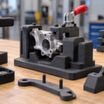
SLS 3D printing for jigs, fixtures and ...
12 October 2026 Comments Off on SLS 3D printing for jigs, fixtures and robotic grippers
Prototyping for automation and industrial engineering: choosing ...
15 September 2026 Comments Off on Prototyping for automation and industrial engineering: choosing the right manufacturing process
Vacuum casting for consumer products: production-quality parts ...
20 August 2026 Comments Off on Vacuum casting for consumer products: production-quality parts without production tooling
Surface finish and colour in consumer product ...
14 August 2026 Comments Off on Surface finish and colour in consumer product prototypes: what’s achievable and how to specify it


Prototyping for Medical Device Development: Choosing the ...
28 July 2026 Comments Off on Prototyping for Medical Device Development: Choosing the Right Process