

- Home
- Downloads & resources
- Prototyping Technologies: A Practical Guide for Engineers and Product Developers
Prototyping Technologies: A Practical Guide for Engineers and Product Developers
Executive Summary
Prototyping technologies have advanced considerably over the past decade, and the pace of development shows no sign of slowing. For engineers and product developers, this creates both opportunity and complexity: more processes are available than ever before, each with a distinct set of capabilities, constraints, and appropriate applications. Making the right choice for a given project, at a given stage of development, has become as important a skill as the design work itself.
This white paper provides a practical overview of the prototyping and low-volume manufacturing technologies available today, covering 3D printing in its various forms, CNC machining, vacuum casting, and the relationship between the prototyping process and injection moulding production. It examines how each process works, where it excels, where it falls short, and how the processes work together across a typical product development programme. It also looks at emerging developments that are beginning to shape how prototype bureaux operate.
The aim is not to provide an exhaustive technical reference, but to give engineers and designers the knowledge they need to make better, faster decisions about how to prototype their products and when to transition to production. A well-run prototyping programme does more than produce parts: it reduces the risk of expensive decisions, surfaces design issues at the point where they’re cheapest to resolve, and builds the evidence base on which a confident move to production tooling can be made.
Introduction: Why Process Selection Matters

The right prototype isn’t the fastest one to produce. It’s the one that answers the question you’re actually asking
Prototyping sits at the heart of good product development. The ability to produce a physical part, test it, learn from it, and revise the design is what separates a well-validated product from one that reaches production carrying assumptions that should have been challenged earlier. Every prototype that fails in testing is a success of the development process; every assumption that passes unchallenged into a production design represents a risk that compounds in cost and complexity the further along the programme it goes.
The challenge for engineers today is not access to prototyping technology. Lead times are shorter, costs are lower, and the range of available processes is wider than at any previous point. The challenge is making good decisions about which process to use, when, and why.
This is not a trivial question. An SLA 3D printed part and a CNC machined aluminium part can both be described as prototypes, but they represent fundamentally different objects with different properties, different limitations, and different appropriate uses. Using the wrong process at the wrong stage costs time and money and can generate misleading test data that leads development in the wrong direction.
The sections that follow examine each major prototyping technology in practical terms, grounded in the capabilities of a full-service UK prototyping bureau serving engineers across medical and life sciences, aerospace and defence, automotive, electronics, consumer products, and general manufacturing.
Section 1. 3D Printing
1.1 What 3D Printing Actually Is
3D printing, or additive manufacturing, is the process of building a part by adding material layer by layer from a digital model. Unlike subtractive processes such as CNC machining, which start with a solid block and remove material, additive processes start from nothing and build up. This fundamental difference has significant implications for what geometries are achievable, what materials can be used, and what the finished part’s properties will be.
It’s worth being precise about what “3D printing” means in a professional prototyping context, because the term encompasses a wide range of processes with quite different capabilities. A desktop filament printer and an industrial SLA machine with a 750mm build platform are both “3D printers” in common usage, but they have little in common in terms of accuracy, surface quality, material range, or appropriate application. This paper focuses on the industrial processes used in professional rapid prototyping.
1.2 Selective Laser Sintering (SLS)
SLS fuses powdered nylon using a laser, building the part inside a bed of powder that acts as its own support structure. Because no separate support material is required, SLS can produce complex geometries, internal features, and interlocking assemblies that would be impossible or very difficult to achieve with processes that require supports.
The resulting parts are strong, tough, and broadly isotropic: their mechanical properties do not vary significantly with build direction. This makes SLS the most appropriate additive process for functional prototypes that will be subjected to real loads, handling, and testing. SLS nylon is not as stiff as an engineering plastic such as acetal or glass-filled nylon, but it is robust enough for most functional applications at the prototype stage.
Surface finish from SLS is slightly textured due to the sintered powder, which distinguishes it visually from injection moulded parts. For many applications, this is acceptable, and finishing operations, including vapour smoothing and dyeing, are available to improve appearance. SLS parts can also be dyed in a range of colours, which opens up possibilities for colour-differentiated assemblies or customer-facing prototypes.
1.3 Stereolithography (SLA)
SLA uses a UV laser to cure liquid photopolymer resin layer by layer. It produces parts with fine surface detail, smooth finish, and good dimensional accuracy, making it the natural choice when appearance, fit, or surface quality is the primary requirement.
SLA parts are inherently isotropic, and the material range covers grades that simulate polycarbonate, ABS, polypropylene, and high-temperature engineering plastics. A key application that is sometimes overlooked is the production of master patterns for vacuum casting: the quality of every vacuum cast part in a production run traces directly back to the quality of the SLA master from which the silicone mould was made.
Build volumes for professional SLA equipment can be substantial. At Prototype Projects, our largest printer is the SLA 750. It offers a build platform of 750 x 750 x 550mm, which means large panels, housings, and structural components can be produced in a single build. This is relevant for sectors such as automotive and aerospace, where prototype parts are often large.
Post-processing is a significant part of the SLA workflow and how a professional bureau adds real value. Build line removal, lacquering, painting, soft-feel coating, optical clarity lacquering for clear parts, and blackout and EMI/RFI coatings for internal surfaces are all available. A finished, painted SLA part can be extremely difficult to distinguish visually from a production injection moulding, which matters for user research, investor presentations, and photography.
An SLA 3D printed part and a CNC machined aluminium part can both be called prototypes. They are not the same object.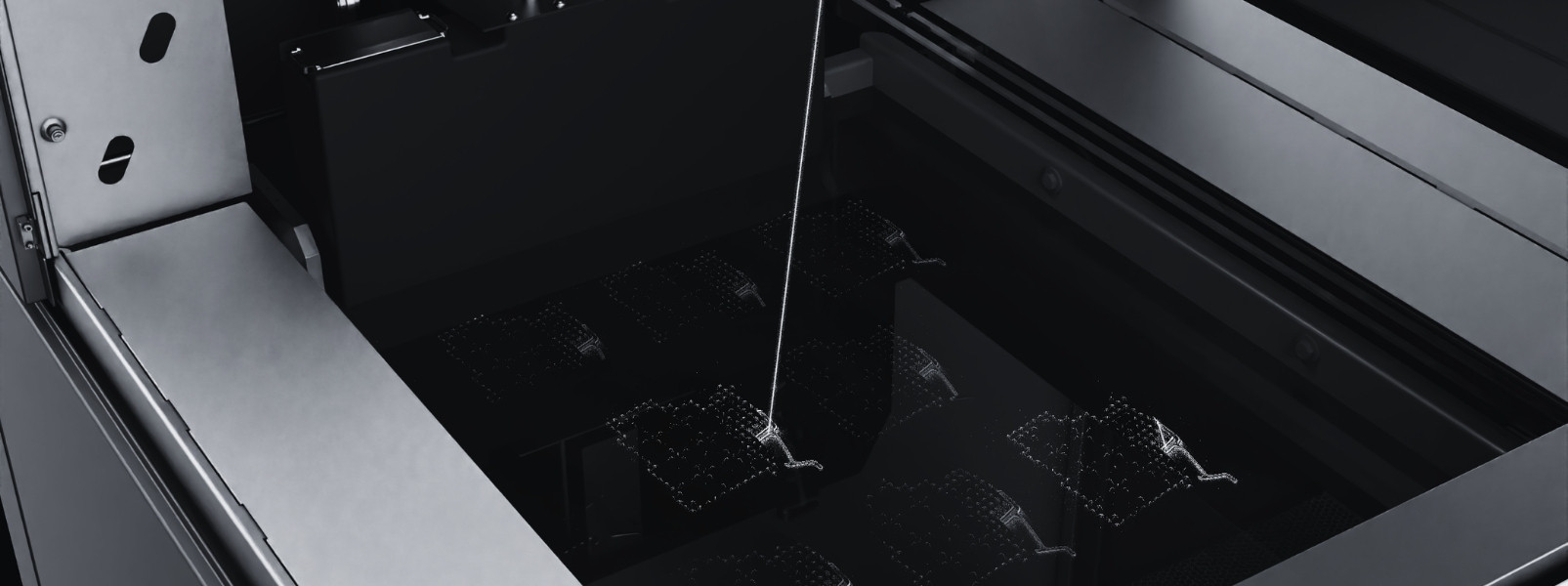
1.4 Projection Stereolithography (PSLA)
PSLA is a hybrid process that combines elements of SLA and DLP, using a projector-based curing system with a fine-detail scan for borders and a broader fill pass for interior areas. The result is a step-change improvement in surface quality compared to standard SLA, achieved without the very long build times that would result from scanning every pixel of every layer at fine resolution.
This process is particularly valuable for consumer-facing prototypes, cosmetic models, and any application where the prototype’s surface quality needs to be close to that of a production moulding without extensive hand-finishing.
1.5 Digital Light Projection (DLP)
DLP cures resin by projecting an entire layer at once rather than scanning it point by point. This makes it faster than SLA for many part sizes, and it is particularly well suited to small, intricate parts with fine detail. DLP also supports a broader range of specialist materials than SLA, including fire-retardant grades, flexible grades, and ultra-high-temperature resins, extending its application range into sectors with specific regulatory or performance requirements.
1.6 Micro 3D Printing
For applications where features are measured in tens of microns rather than millimetres, conventional SLA and DLP reach their practical resolution limits. Micro 3D printing using Projection Micro Stereolithography (PµSL) addresses this with an XY optical resolution of 10 microns and layer thicknesses down to 10 microns, enabling feature sizes that are simply not achievable by any other additive process.
The primary applications are in medical devices, microfluidics, photonics, lab-on-chip components, and micro-electronics, where the geometry of the part is the product and conventional manufacturing alternatives such as micro CNC machining would involve substantially greater cost and lead time at the prototype stage. Available materials include biocompatible grades that have passed ISO 10993 testing, which extends applicability into patient-contact medical device development.
1.7 Filament 3D Printing
Filament-based printing (FDM/FFF) deposits molten thermoplastic layer by layer. It’s the most widely available and least expensive form of 3D printing, and for certain applications it remains the right choice: large, simple parts in ABS or ASA, jigs and fixtures, early-stage concept models where fine detail is not critical. Its limitations in surface quality, dimensional accuracy, and part anisotropy mean it is rarely the appropriate choice for functional prototypes in professional product development, but it is a useful tool when those limitations don’t matter.
Section 2. CNC Machining
2.1 What CNC Machining Offers That Additive Processes Cannot
CNC machining is a subtractive process: it starts with a solid block of material and removes everything that isn’t the part. The fundamental consequence of this is that the material is homogeneous and isotropic throughout. A CNC machined aluminium part has the same material properties as a billet of aluminium 6082; a CNC machined acetal part behaves exactly as the material datasheet describes. There is no layer interface to weaken, no build orientation to consider, no residual stress from a curing process.
For functional prototype testing, this is critical. Where a prototype will be loaded, fatigue tested, subjected to thermal cycling, or used to validate a structural analysis, the test data needs to represent the behaviour of a part with consistent material properties. CNC machining provides this. Most 3D printing processes do not.
Dimensional accuracy is the other major consideration. The quoted general tolerance at Prototype Projects is ±0.1mm, which is a conservative starting point for estimating. In practice, the machine tools hold considerably tighter on critical dimensions, and specific tolerances can be agreed on individual features when the application requires it. This level of control is particularly relevant for parts with bearing bores, mating surfaces, threaded features, and close-tolerance interfaces that will be assembled with other components.
2.2 CNC Milling
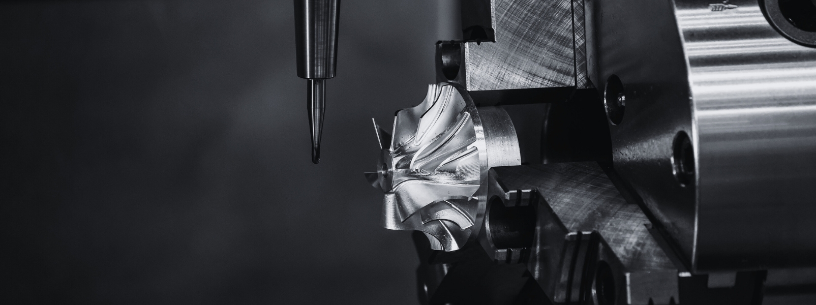
CNC milling uses rotating cutting tools to produce profiles, pockets, slots, and complex 3D surfaces from a solid block. Three-axis milling is capable of producing a wide range of features from a fixed workpiece orientation. Five-axis milling adds two additional rotational axes, allowing the tool to approach the workpiece from a much wider range of angles. This is not merely a matter of convenience: it means that complex parts with features on multiple faces can often be completed in a single setup, which reduces both cycle time and the accumulation of positional errors that can occur when a part is repositioned between operations.
Prototype Projects operates two Haas VF-2SSYT five-axis vertical machining centres alongside a range of three-axis centres and mini mills. The five-axis machines are equipped with Schunk air vices and Haas robot packages for automated part loading and unloading, enabling unattended batch production and supporting the low-volume manufacturing service alongside the prototype offering.
Offline programming using Mastercam processes customer STEP, IGES, and X_T files directly, generating toolpaths for complex geometries without the need for redrawing or remodelling.
2.3 CNC Turning
Turning is used for cylindrical parts: shafts, bushes, connectors, fittings, and any component with a primary rotational form. The workpiece rotates against a fixed cutting tool, which traverses along it to produce the required diameter, profile, and length. Turned parts may also have drilled, bored, or tapped features added during the turning operation.
Many prototype parts require both milling and turning operations. Having both processes available in-house avoids the delays and handoff risks that arise when work has to be split between suppliers, meaning a single quote, single point of contact, and single delivery covers the complete part.
2.4 The 3-Day CNC Service
For projects where speed is the defining constraint, Prototype Projects offers a 3-day CNC machining service for parts that meet defined criteria. The service is built around in-stock material billets in fixed sizes, a defined set of standard operations, and a workflow specifically organised to deliver dispatch within three working days of receiving final CAD data.
Available materials for the 3-day service are aluminium 6082, acetal (black and natural), and clear acrylic, in billet sizes from 50 x 50 x 40mm up to 200 x 100 x 90mm for milling, and up to 60mm diameter for turning. Standard threads from M2 to M12 are supported. All parts are vapour honed as standard and inspected to basic visual and CAD comparison before dispatch.
The importance of this service extends beyond simple convenience. In a compressed development timeline, the number of design iterations possible before a programme milestone is determined partly by the speed at which each iteration can be turned around. A three-day turnaround from CAD to physical part means that a design change identified on a Monday can be in the engineer’s hands and on the test rig by Thursday.
2.5 Low-Volume Production
The same characteristics that make CNC machining well suited to prototype parts, accuracy, material integrity, and repeatability also make it practical for low-volume production of parts that are not suitable for, or do not yet justify, injection mould tooling. The five-axis machines with robotic loading are configured to run batches of identical parts unattended, which brings per-part cost down as quantity increases.
This service is relevant for products with annual volumes in the range of tens to low hundreds, for bridge production while mould tooling is being made, and for parts in regulated sectors where the traceability and material integrity of machined components are preferred over moulded equivalents.
2.6 Materials for CNC Machining
The range of materials available for CNC machining is substantially wider than for 3D printing. The most commonly used at the prototype stage fall into two categories.
Metals include aluminium 6082 and 7075, stainless steel 304 and 316, mild steel, brass, and copper. Aluminium 6082 is the most frequently specified for prototype work: it machines well, produces a good surface finish, and offers useful strength and corrosion resistance at low weight. Aluminium 7075 is the choice for higher-strength applications. Stainless steel is specified where corrosion resistance is the primary requirement; 316 offers greater resistance to chlorides than 304, which is relevant for medical and marine applications.
Engineering plastics include acetal, nylon, PEEK, clear acrylic, and polycarbonate. Acetal is the most widely used: it’s dimensionally stable, machines cleanly, has low friction, and resists moisture. Nylon offers toughness and fatigue resistance, making it appropriate for gears, cams, and sliding components. PEEK is the choice for applications with demanding combinations of temperature resistance, chemical resistance, and mechanical performance. Clear acrylic and polycarbonate are specified where optical transparency is needed.
Tighter tolerances than the application requires don’t make a better prototype. They make a more expensive one.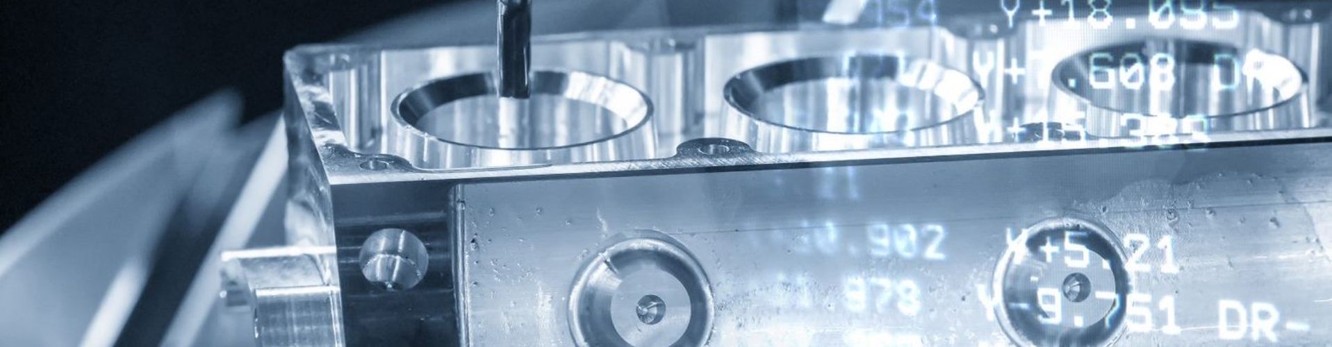
2.7 Inspection
All CNC machined parts are deburred, cleaned, degreased, and inspected before dispatch. Standard inspection uses callipers, micrometres, and thread gauges to check key dimensions. For applications requiring a higher level of dimensional verification, Prototype Projects operates an in-house co-ordinate measuring machine (CMM), which uses a contact probe to measure surface positions in three dimensions and compare them against the CAD model.
CMM inspection is particularly relevant for parts with critical bores, mating interfaces, hole patterns, and geometric tolerances, including flatness, parallelism, perpendicularity, and concentricity. Formal inspection reports can be provided where required, which is important for customers in regulated sectors. Having CMM capability in-house, rather than relying on a third-party metrology supplier, means dimensional issues are identified before a part leaves the site rather than after it has been assembled into a test rig or submitted for regulatory review.
Section 3. Vacuum Casting
3.1 The Process and Its Place in the Workflow
Vacuum casting in polyurethane is the bridge between individual 3D printed prototypes and injection moulded production. When a project reaches the stage where a batch of parts is needed, whether for user testing, regulatory submission, assembly line trials, or early market supply, and where the cost and lead time of an injection mould tool are not yet justified, vacuum casting provides a practical and cost-effective solution.
The process begins with an SLA master pattern, hand-finished to the required surface standard. A silicone rubber mould is poured around the master under vacuum, cured, and then cut open to release the pattern. The mould is reassembled and used to cast liquid polyurethane under vacuum, producing parts that faithfully replicate the master’s surface finish and geometry, including fine details and snap fits. Each silicone mould is reusable for up to 25 castings, depending on geometry and material, making it practical and economical for small batches.
3.2 Materials
Polyurethane resins span a wide range of properties. Elastomeric grades cover Shore A hardnesses from 25 to 95, simulating thermoplastic elastomers from soft rubber to firm flexible plastic. Rigid grades simulate ABS, acetal, polypropylene, unfilled nylon, and glass-filled nylon. Specialist grades include water-clear formulations for transparent parts, fire-retardant grades for specific safety requirements, and heat-resistant grades for thermal testing applications.
The material properties of cast polyurethane correspond directly to the grade used, and parts are isotropic, non-porous, and water-resistant, characteristics that 3D printed parts cannot consistently match. This makes vacuum cast parts suitable not only for prototyping but for end-use applications in lower-volume products.
Vacuum casting sits between the individual prototype and the injection moulded production run – and it’s often the most underused step in the process.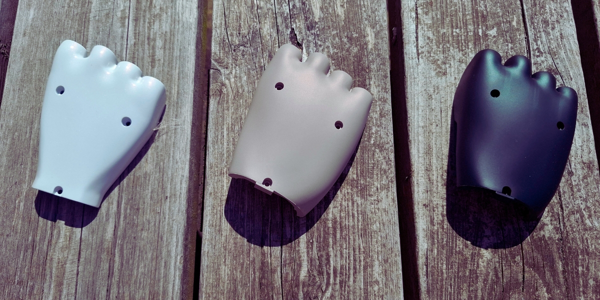
3.3 Overmoulding and Assembly
Vacuum casting is the most practical process for overmoulding at the prototype stage. Adding an elastomeric layer to a rigid substrate, encapsulating a metal component, or producing a soft-feel grip over a structural core are all achievable. Threaded inserts can be cast in place, and vacuum cast parts can be assembled with CNC machined, 3D printed, or off-the-shelf components. Post-processing options include blackout and EMI/RFI coatings for internal surfaces and vacuum metallising for premium surface finishes.
Section 4. Injection Moulding and Its Relationship to the Prototyping Process
4.1 Why Injection Moulding Belongs in a Prototyping White Paper
Injection moulding is not a prototyping technology. It is a production technology, and in most product development programmes, it represents the destination rather than the journey. Understanding it matters in a prototyping context for a straightforward reason: every decision made during the prototype stage has implications for the injection moulded part that will eventually follow. The earlier those implications are understood, the less likely they are to become expensive problems.
A prototype that has been designed without reference to mouldability constraints may validate the design intent perfectly well, but then require significant rework before a mould tool can be cut. Wall thickness transitions that cause sink marks, features that prevent ejection, internal geometries that can’t be filled, draft angles that haven’t been considered: these are all issues that a good prototyping programme should surface and resolve before tooling investment is committed, not after.
Working with a bureau that understands injection moulding during the prototype phase, not just at the production stage, means that design for manufacture considerations can be introduced at the point where they’re cheapest to address.
4.2 Prototype Injection Moulding: The Options Between Casting and Full Production Tooling
The economics of injection moulding are well understood. A production-quality steel mould tool represents a significant capital investment, with lead times typically measured in weeks. For high-volume production, it is the obvious choice: per-part cost is low, cycle times are fast, and the full range of thermoplastic materials is available. But for quantities of a few hundred parts, or for a design that hasn’t yet been fully validated, the investment is harder to justify.
Between vacuum casting, which is practical up to around twenty-five parts per mould, and full production steel tooling, there is a middle ground that is often underused: prototype or bridge injection moulding using aluminium tooling.
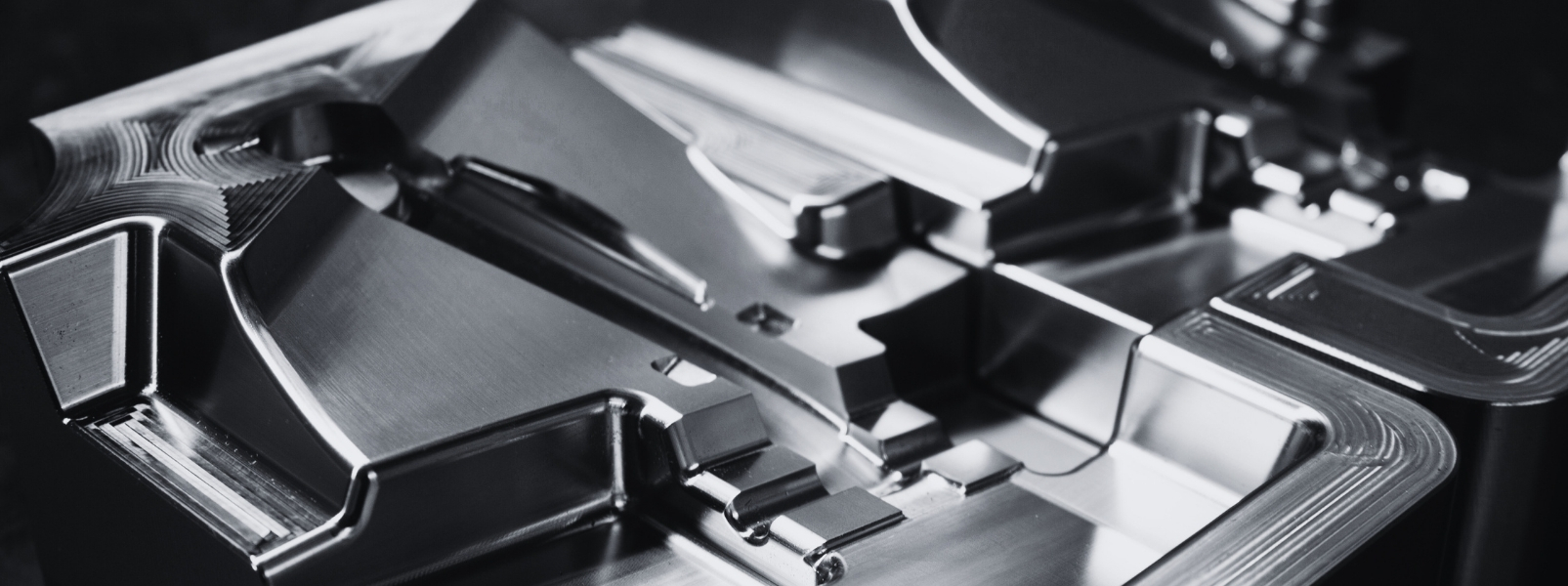
Aluminium mould tools are less expensive and faster to produce than steel equivalents. They don’t have the longevity of steel – an aluminium tool is typically rated for thousands of shots rather than hundreds of thousands – but for bridge production, market testing, regulatory submission quantities, or early customer supply while the production tool is being made, they are a practical and cost-effective option. Parts produced from an aluminium mould are genuine injection mouldings in genuine thermoplastic materials, which means the test data and the approval documentation they generate are directly relevant to the production part.
4.3 When to Move from Prototyping to Tooling
One of the most common questions in a product development programme is when to commit to mould tooling. The answer depends on volume, confidence in the design, and the cost of getting it wrong.
As a rough framework: vacuum casting makes economic sense up to quantities of around twenty-five parts per mould, sometimes more for simple geometries and less for complex ones. CNC machining can bridge to higher quantities for the right parts and materials, particularly on five-axis equipment with automated loading. Beyond that, the per-part cost of non-moulded production typically exceeds the amortised cost of tooling, and the move to injection moulding becomes justified.
The design confidence question is equally important. Committing to a steel production tool for a design that hasn’t been fully validated through functional prototyping is a risk. Changes to a steel tool after it has been cut are expensive and time-consuming, and some changes are simply not possible without scrapping the tool and starting again. The prototyping programme exists, in part, to reduce that risk to an acceptable level before tooling is ordered.
A useful discipline is to treat the final vacuum casting run as a pre-production sign-off. If the vacuum cast parts pass functional, dimensional, and cosmetic review, and if any feedback from user testing or regulatory review has been incorporated into the design, that is a reasonable point at which to commit to tooling. The silicone mould used for vacuum casting and the SLA master that preceded it represent a design history that supports the tooling decision.
4.4 Design Considerations That Bridge Prototype and Production
Several design features that are straightforward to produce in prototyping processes need to be reconsidered when the same part moves into injection moulding. Being aware of these during the prototype stage, rather than encountering them as surprises at the tooling stage, saves time and cost.
Draft angles are not required for CNC machined or vacuum cast parts, but they are essential in injection moulding to allow the part to eject cleanly from the tool. Vertical walls in a prototype design will need draft added before tooling. The appropriate angle depends on surface finish and material, but 1 to 2 degrees per side is a common starting point.
Wall thickness should be as uniform as practical in an injection moulded part, to promote even filling and cooling and to avoid sink marks on external surfaces. CNC machining and vacuum casting are more tolerant of varying wall sections, which means a prototype may pass functional testing with a wall design that would cause cosmetic or structural problems in a moulding.
Internal corners present differently in the two processes. CNC machining leaves radii at internal corners due to tool geometry; injection moulding benefits from radii at internal corners for flow and strength reasons, but the geometry of those radii is driven by mould filling and stress concentration rather than by tooling constraints.
Undercuts achievable in CNC machining or vacuum casting may require side actions or lifters in an injection mould tool, which add cost and complexity. Identifying these features during the prototype review stage allows the designer to consider whether the undercut is genuinely necessary or whether a design modification would simplify the eventual tool.
Material selection for prototyping inevitably involves compromise. SLA resins simulate ABS or polycarbonate; SLS nylon approximates unfilled nylon; vacuum cast polyurethane simulates a range of engineering plastics. None of these is the production material. Functional test data generated from prototypes should be interpreted with this in mind, and where material properties are critical to the test outcome, the most representative simulant should be selected deliberately rather than by default.
4.5 Injection Moulding at Prototype Projects
Working with a single supplier across both the prototyping and moulding phases means the transition from prototype to production part carries a continuous design history. The friction of transferring design intent, inspection criteria, and programme context to a new supplier at a critical point in the development timeline is avoided, and with it, the risk of something important being lost in the handover.
It also means that the team advising on the prototype design is aware of the moulding implications from the outset. That awareness is most valuable early, when design decisions are still easy to change, rather than at the point where tooling is being quoted, and the cost of revision is already high.
Section 5: Choosing the Right Process
One of the most common questions a prototyping bureau is asked is: which process should I use? The honest answer is that it depends on what you need the prototype to do, what stage of development you’re at, and what comes next. But some consistent principles help frame the decision.
If you need speed above everything else and the part is simple enough to qualify, CNC machining on a 3-day service delivers a machined metal or plastic part faster than almost any alternative. Overnight SLS or SLA printing is available for 3D printed parts and is appropriate where the material properties of a machined part are not required.
If you need functional material properties, CNC machining is the default choice. The isotropy and consistency of machined material cannot be replicated by any current additive process for a general engineering audience.
If you need complex geometry that machining cannot produce, SLS is usually the right 3D printing choice for functional parts because it combines geometric freedom with the best mechanical performance of any additive polymer process. SLA is the choice when surface quality is the priority.
If you need a small batch of production-representative parts, vacuum casting from an SLA master is typically the most cost-effective route for quantities of five to twenty-five. It delivers parts with consistent material properties, production-quality surface finish, and a per-part cost that drops significantly once the mould is made.
If your features are in the micron range, micro 3D printing using PµSL is the only additive process capable of resolving them. The question is whether the part geometry and size fall within the 100 x 100 x 75mm build envelope.
In practice, most product development programmes use multiple processes in combination. A concept model in SLA, a functional prototype in SLS or CNC, a batch of pre-production parts via vacuum casting, and low-volume production in CNC while injection mould tooling is in progress: this is a common sequence, and understanding how the processes relate to each other makes it easier to plan the development programme efficiently.
Section 6: Emerging Developments
6.1 AI-Assisted CAM Programming
Programming CNC toolpaths has traditionally required a skilled programmer to work through the geometry, select appropriate tooling and cutting strategies, and optimise feeds, speeds, and approach paths manually. AI-assisted CAM tools, including platforms such as CloudNC, are beginning to automate significant portions of this workflow by learning from libraries of successful cutting strategies and applying them to new geometries. The practical effect is a reduction in programming time for complex parts, which has implications for lead time and quoting speed. These tools are most effective on well-understood part types and materials; complex, novel geometries still benefit from experienced programmer oversight.
6.2 Robotics and Automation in Machining
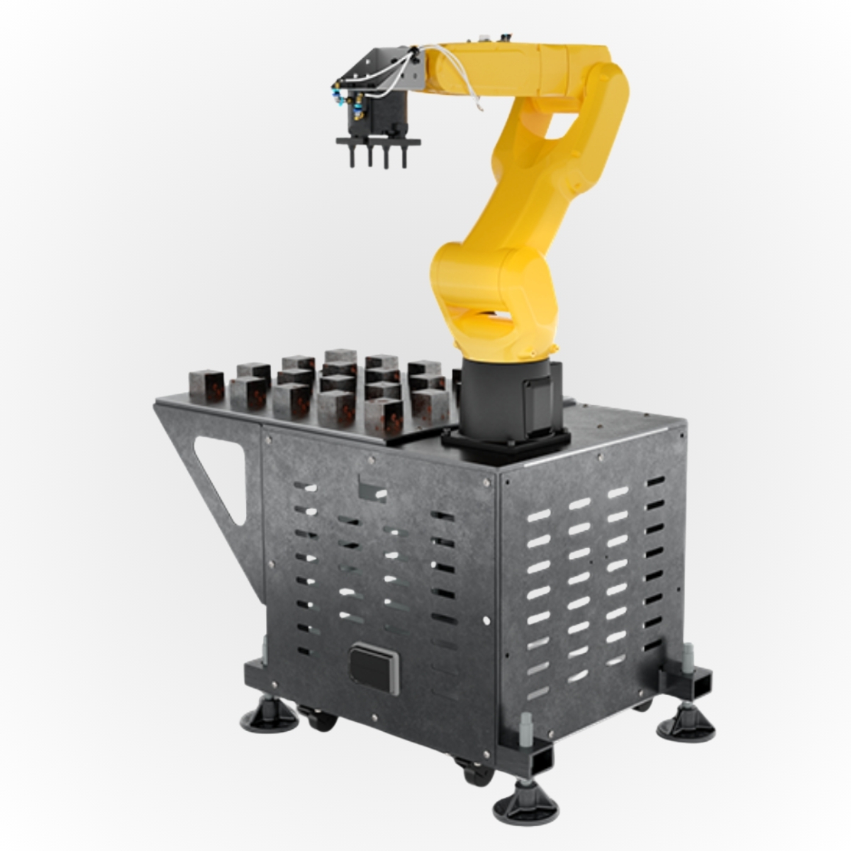
The integration of robotic loading and unloading into CNC machining centres extends the operational hours of expensive capital equipment beyond the working day. When a five-axis machining centre can load its own blanks, machine parts, and unload finished components unattended overnight, the effective capacity of the machine increases substantially without a proportional increase in labour cost. This matters for the economics of low-volume production, where per-part cost needs to be kept competitive with alternatives such as injection moulding for the service to be viable.
6.3 Material Development in Additive Manufacturing
The rate of new material development for industrial 3D printing processes continues to accelerate. In SLS, high-performance polymers and composite-filled grades are extending the mechanical performance of printed parts toward territory previously occupied only by CNC machined engineering plastics. In DLP, fire-retardant and ultra-high-temperature resins are opening applications in aerospace, automotive, and electronics that were previously inaccessible to resin-based printing. Biocompatible materials validated to ISO 10993 are extending micro 3D printing into medical device applications where direct patient contact is involved.
6.4 Convergence of Inspection and Manufacturing
The separation between manufacturing and inspection is becoming less distinct as measurement capability moves closer to the point of production. In-process measurement, where a CMM or optical measurement system verifies dimensions during the machining cycle rather than after it, is increasingly practical on well-equipped machining centres. For prototype work, where each part may be unique and first-off inspection is critical, this reduces the time between machining and confirmed dimensional acceptance, supporting faster iteration.
6.5 Sustainability in Prototyping
Environmental considerations are increasingly part of the procurement discussion for prototyping services. The relevant factors include material waste, which is inherently higher for subtractive processes than additive processes; energy consumption per part, which varies considerably between processes; and the availability of recycled or recyclable materials. In SLS, unsintered powder is typically recycled back into subsequent builds at a proportion determined by the supplier, reducing material waste. In CNC machining, swarf (metal cutting chips) is collected and recycled through established metal recycling channels. These are not marginal considerations: for companies with published sustainability commitments, the environmental profile of their supply chain is subject to scrutiny, and a prototyping supplier that can account for its material and energy usage is better placed to support those commitments.
Conclusion
The prototyping technologies available to engineers today represent a genuinely broad toolkit. SLS, SLA, PSLA, DLP, micro 3D printing, CNC milling, CNC turning, and vacuum casting each have distinct capabilities, and the skill in using them effectively lies in matching the right process to the right requirement at the right stage of development.
No single process dominates. The most effective product development programmes use multiple technologies in sequence and in combination, taking advantage of the speed of additive manufacturing for early-stage iteration and the material integrity of CNC machining for functional validation. Vacuum casting provides the bridge between individual prototypes and volume production, and micro 3D printing opens up application areas that no other process can reach.
Underlying all of this is a purpose that is easy to lose sight of when the focus is on individual processes and individual parts: prototyping exists to de-risk the move to production. Every functional test passed, every design issue surfaced and resolved, and every pre-production batch reviewed brings a programme closer to the point at which tooling investment can be committed with confidence. The prototyping programme is not separate from the production decision – it is the evidence base on which that decision rests.
That is why the relationship between prototyping and injection moulding matters, and why working with a supplier who understands both and can take a project from first concept model to moulded production part is a different proposition from working with one that specialises in only part of the journey. Continuity of design intent, inspection criteria, and programme context across that transition is not a minor administrative convenience. It is a meaningful reduction in risk at a critical programme milestone.
For engineers working on time-critical programmes, the choice of prototyping supplier matters as much as the choice of process. A bureau that offers a genuinely broad process portfolio, in-house inspection capability, and the flexibility to accommodate urgent requirements is a different resource from one that does only additive manufacturing or only CNC work. The ability to move a project between processes as development progresses, without changing supplier, saves time and reduces the risk of design intent being lost in translation.
Begin your journey
Whether you’re at the concept stage or preparing for pre-production, we can help with 3D Printing, CNC Machining, Vacuum Casting, Injection Moulding, Model Making, and more. We’re particularly used to working with product teams on tight timelines and to working through finishing requirements in detail before a job goes into production.
Use our online quoting platform, Matrix, to get instant quotes and place orders for SLS, SLA and DLP 3D printing. Otherwise, request a quote or contact us on 01763 249760 to discuss your needs.