


- Home
- CNC Machining
- Understanding CNC Machining Tolerances
Understanding CNC Machining Tolerances
When specifying CNC machining tolerances, it’s easy to default to tight numbers across an entire drawing. ±0.1 mm feels safe. ±0.05 mm feels even safer.
But what do those numbers actually mean in practice? And when do they add unnecessary cost?
Understanding machining tolerances properly can reduce lead time, improve manufacturability and lower production cost without compromising performance.
What is a machining tolerance?
A tolerance defines how much a dimension is allowed to vary from its nominal value. If a feature is specified as 20 mm ±0.1 mm, the acceptable range is 19.9 mm to 20.1 mm.
In CNC machining, achievable tolerances depend on:
- Material type
- Part geometry
- Machine capability
- Tool condition
- Fixturing stability
- Environmental factors
For general CNC machining, ±0.1 mm is widely achievable. Tighter tolerances are possible, but they often require additional setups, slower machining speeds or secondary finishing operations.
Why tighter tolerances increase cost
Every time a tolerance tightens, risk increases. To manage that risk, machinists must:
- Reduce feed rates
- Increase inspection frequency
- Use specialised tooling
- Allow for additional finishing passes
- Potentially scrap more parts
This increases machining time and quality control effort.
Specifying ±0.02 mm on non-critical features does not improve performance. It simply increases cost and lead time.
The key question should always be: Does this feature genuinely need that level of control?
General tolerances vs critical tolerances
A practical approach is to apply:
- A general tolerance for most features
- Specific tighter tolerances only where function demands it
Critical features often include:
- Bearing fits
- Sealing faces
- Mating components
- Alignment features
- Press-fit diameters
By isolating these areas, you allow the rest of the part to be machined more efficiently.
Tolerance stacking and assemblies
Tolerance stacking becomes important when multiple components interact.
Individually acceptable variations can accumulate in assemblies, leading to misalignment or performance issues. This is where careful tolerance strategy and, where appropriate, GD&T become valuable.
However, over-complicating drawings can also slow production. Clear communication between design and machining teams is often more effective than layering complexity into every feature.
Inspection and verification
Achieving a tolerance is one thing. Verifying it is another.
Inspection methods may include:
- Digital callipers or micrometers
- Height gauges
- CMM inspection
- Surface measurement tools
The tighter the tolerance, the more rigorous the inspection process. That inspection time is part of the overall cost.
A balanced approach
The most effective CNC designs:
- Apply tight tolerances only where function demands
- Use standard hole sizes and threads where possible
- Avoid unnecessarily tight flatness or parallelism requirements
- Consider how the part will be fixtured
If you are unsure whether a tolerance is appropriate, a short DFM discussion before machining can prevent delays later.
Good tolerance strategy is not about pushing limits. It is about aligning design intent with manufacturing reality.
CNC Tolerances in Practice
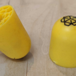
At Prototype Projects, our general quoted tolerance is ±0.1 mm – already considerably better than what most 3D printed parts can achieve. In reality, CNC machining is usually accurate to much less than ±0.1 mm, and critical dimensions can be held to tighter tolerances on request.
Understanding this helps engineers make smarter decisions about when CNC machining is the right solution for prototypes, low-volume runs, or precision components.
Ready to explore how CNC machining could benefit your next project?
Visit our CNC milling and CNC turning pages or contact us on 01763 249760 to discuss your requirements with our team.

What CNC Machining Can’t Do: A Designer’s ...
31 March 2026 Comments Off on What CNC Machining Can’t Do: A Designer’s Guide to the Real Constraints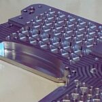
CNC Machining for Prototypes: Speed, Accuracy and ...
25 March 2026 Comments Off on CNC Machining for Prototypes: Speed, Accuracy and Material Choice
PSLA vs SLA vs DLP | Resin ...
18 March 2026 Comments Off on PSLA vs SLA vs DLP | Resin 3D Printing Comparison
New Larger CNC Billet Expands 3-Day and ...
10 March 2026 Comments Off on New Larger CNC Billet Expands 3-Day and Production Capacity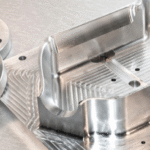
Stainless Steel 304 vs 316 for CNC ...
5 March 2026 Comments Off on Stainless Steel 304 vs 316 for CNC Machining: When Does the Upgrade Make Sense?


Understanding the Difference Between CNC Milling and ...
15 April 2025 Comments Off on Understanding the Difference Between CNC Milling and CNC Turning for Better Design Choices